Experimental Investigation of a New Ammonia Synthesizer for Practical Applications
Progress Report 2
Faculty of Engineering and Applied Science
University of Ontario Institute of Technology
Project Leader: Prof. Dr. Ibrahim Dincer
Team members: Haris Ishaq (PhD student)
Ghassan Chehade (PhD student)
Osamah Siddiqui
(PhD student)
Abstract
In this report, we describe the development, analysis and experimental investigation of the environmentally benign portable ammonia synthesizer. The design of the proposed synthesizer is described explaining the different sub-processes involved. Further, the modelling and simulation of the synthesizer is performed in ASPEN Plus software. The analysis results provide an input power of 37 kW when the rate of ammonia production entails a value of 500 L/day. The rate of conversion is found to be 0.48 when the operating pressure of 200 bar and operating temperature of 500oC is employed. Also, the operating conditions are varied and their effects on the system performance are investigated. Higher operating pressures provide higher conversion and higher operating temperature reduce the conversion ratios. In addition, the experimental ammonia synthesizer developed is described and the functionality of the associated subsystems is elucidated. Moreover, both the initial prototype as well as the optimized system are presented. The experimental results obtained with different types of catalysts are also discussed.
- Introduction
The massive usage and dependence on fossil fuels has caused various detrimental and alarming effects on the environment. To overcome these harmful effects, the usage of fossil fuels needs to be reduced. Ammonia production today relies on steam methane reforming to obtain hydrogen that entailed massive environmental emissions. However, ammonia is a good candidate that can be utilized in the power generation industry along with several other applications. In addition to this, hydrogen is expected to play a key role in overcoming the dependency on fossils. Nevertheless, owing to various disadvantages entailing its usage, hydrogen usage as a clean fuel has been hindered. These include firstly low density that poses challenges with storage as well as transportation. Also, there are several concerns regarding the safety of hydrogen usage. Entailing no odor, hydrogen leakage is difficult to detect.
On the other hand, ammonia entails solutions several problems that hydrogen poses. It entails a high density and can be easily liquefied allowing significant ease in storage as well as transportation. In addition, ammonia entails a high percentage of hydrogen that allows it to be used as a chemical means of hydrogen storage. Further, ammonia is associated with several applications that include fertilizers, refrigeration, power generation etc. When used for power generation, ammonia is expected to result in no harmful emissions such as carbon dioxide or carbon monoxide. At present, the conventional production of ammonia takes place in large quantities at ammonia synthesis plants that utilize the Haber-Bosch process. This process makes ammonia production centralized and entails massive harmful environmental emissions. Thus, there is a need to develop new ammonia synthesis systems that can produce ammonia in a decentralized and environmentally benign manner. The primary detrimental emissions associated with ammonia synthesis are associated with steam methane reforming used for hydrogen production. Hence, water electrolysis is a promising way to produce clean hydrogen that can utilized for ammonia synthesis. In addition, conventional plants utilized cryogenic air separation for obtaining nitrogen, however, this is highly energy intensive and requires very low refrigeration temperatures. Therefore, in this project we design, develop and investigate an environmentally benign and portable ammonia synthesis system that operates with material inputs of air and water along with an electrical input.
- System Description
The schematic of the developed ammonia synthesizer is presented in Figure 1. The system input of air enters the developed system at state 1. It enters the pressure-swing adsorption (PSA) nitrogen generation subsystem. In the PSA subsystem, the air entering the system undergoes the process of adsorption over carbon molecular sieves that preferentially adsorb oxygen and the remaining nitrogen gas exits the subsystem. The compressor pressurizes the input air that enters at atmospheric pressure to achieve satisfactory adsorption. Through a series of adsorption and desorption the nitrogen is extracted form input air.
At present, commercial ammonia generation relies on natural gas for to produce the required hydrogen. This entails colossal environmental detriments and emissions that have various adverse effects. Thus, environmentally benign hydrogen generation should be used. In the developed system, the production of hydrogen is carried out using water electrolysis that can be operated via clean electricity. Water is input to the system at the electrolyzer as shown in the figure. Water is dissociated electrochemically into oxygen and hydrogen. The developed system utilizes a proton exchange membrane (PEM) electrolyser and intakes electrical power as input. The overall reaction for this process is depicted by the equation below:
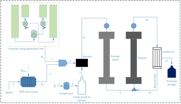
Figure 1 Schematic of the ammonia synthesis system
The flow control valves are employed to provide the required amount of hydrogen as well as nitrogen input flows to the ammonia synthesizer. Both reactants that are produced onboard are compressed to high pressures via a gas booster. The gas booster utilizes compressed air as the input and compresses the reactants to high pressures needed for the ammonia synthesis reaction. The gas booster requires a compressed air input that is provided via an air compressor that is allowed to compress air that is stored in a storage tank. The booster compresses the reactants into a preheater that entails the reactants at the required pressure. The preheater allows the reactant mixture to achieve the desired reaction temperatures. Once, the reactant mixture achieves the required conditions, it is allowed to enter the synthesis reactor. The synthesis reactor is a tubular reactor that includes beds of ammonia synthesis catalyst. The chemical reaction depicting this synthesis process can be written as follows:
(2)
In a single pass not all the reactant molecules obtain a chance to react and form the product ammonia. Thus, recycling is an essential process in ammonia synthesis. The output of the synthesis reactor is passed through a condenser that liquefies the formed ammonia that separates and settles down as a virtue of its density. The other unreacted hydrogen and nitrogen are allowed to re-enter the synthesis reactor through the recycling loop.
- Analysis
The designed methodology targets to develop a fridge size ammonia synthesizer. Aspen Plus commercial software is used to simulate the environmentally benign ammonia production system. Figure 2 displays the Aspen Plus flowsheet of the ammonia synthesizer. The major components employed in the system are; proton exchange membrane (PEM) electrolyser which produces hydrogen, a pressure swing absorption (PSA) unit which produces nitrogen, a booster which compresses mixture of nitrogen and hydrogen, a storage vessel which stores the mixture, a reactor filled with catalyst and a condenser which separates ammonia and recirculates unreacted gases back to the reactors.
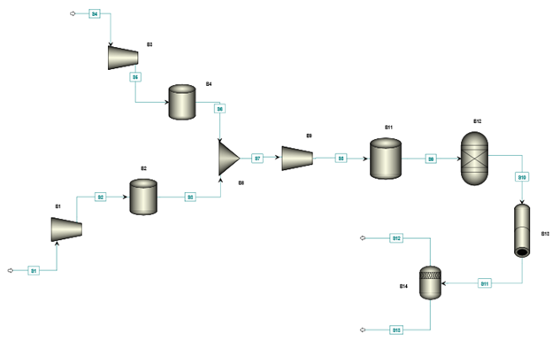
Figure 2 Aspen Plus flowsheet of the designed system
A pressure swing absorption unit is employed to separate nitrogen from air and a proton exchange membrane electrolyzer is used to produce hydrogen. The compressors B1 and B2 compress the hydrogen and nitrogen to a storage vessels upto a desired pressure. Once desired pressure is achieved, mixture of gases is compressed through a gas booster (B9) which uses compressed air cylinder for compression purpose. The mixture of gases is stored in a storage vessel (B11) which is further connected with the reactor vessel (B12) filled with reactor. The input gases are then introduced to the reactor at desired temperature and pressure in the presence of the catalyst. The output from the reactor passes through a condenser which separates ammonia from the unreacted gases and recycles unreacted gases back to the ammonia synthesis reactor.
- Results and Discussion
Figures 3-5 exhibit the achieved results from the parametric studies and sensitive analysis conduced on the designed ammonia synthesizer. Figure 3 shows the relation of the input power with the ammonia production capacities. A direct relation is observed in the power input requirement and the ammonia production owing to the higher inputs required. It can be depicted that the input power rises from 7.2 kW to 37 kW in order to increase the ammonia synthesis capacity from 100 L/d to L/d. The rise in the compressor work and electrical input required by PEM electrolyzer are displayed separately in the parametric study. The temperature and pressure plays a key role in deciding the conversion ratio in the ammonia synthesis reactor which are investigated in Figure 4 and 5. It can be depicted the increase in temperatures causes decrease in the conversion ratios and rise in pressure is observed to upsurge the conversion ratios and eventually ammonia production capacities.
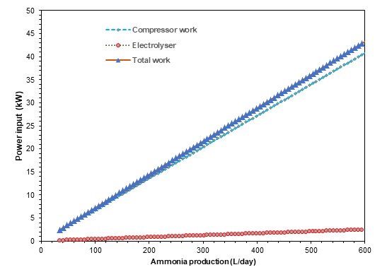
Figure 3 Power input vs ammonia production rate
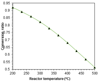
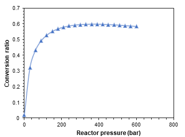
The present system is investigated under different operating conditions of temperature, pressure, production capacities and power input and several parametric studies and sensitivity analyses are also presented to examine the system performance. According to the optimum conditions, the pressure lower than 150 bar can be employed. Additionally, the optimum temperature established for the higher conversion ratio was in the range of 350 to 400 ℃.
5. Experimental Investigation
Ammonia can be synthesized at low pressure by the use of selective continuous mixing tubular reactor. In the proposed system, hydrogen is produced electrochemically by water splitting while nitrogen is separated from air by pressure swing. When hydrogen and nitrogen are presented in the reactor ammonia is produced at high temperature and pressure, the conversion is often limited by the reverse reaction, which makes this reaction only feasible at high pressures. The limitation of the high pressure can be adjusted if the volume of ammonia produced in removed from the reactor. This can be approached by continuous mixing of reactants and products such of fluidized bed reactor. However, the conversion rate can be also limited to the rate of the recycle of unreacted gases. Figure 6 displays the third different generation of the experimentally developed system. In the third generation, the size is further reduced to support the portability of the ammonia synthesizer.

6. Closing Remarks
In this report, the design, modelling and analysis of an environmentally benign ammonia synthesizer is presented. The ammonia synthesizer configuration entails a fridge size that increases its portability as well as compatibility with a wide variety of applications. The developed model of the proposed fridge size ammonia synthesizer is presented. The ammonia synthesizer system is simulated and analysed in Aspen plus and Engineering equation solver software. Some parametric studies are also conducted to analyse the effect of changing system parameters on the system performance. Increasing reactor temperatures are found to decrease the conversion ratios and increasing pressures are observed to provide higher conversion ratios. Furthermore, for an ammonia production rate of 500 L/day, a power consumption of approximately 37 kW is evaluated.
References
- Bicer Y, Dincer. I, Life cycle assessment of nuclear-based hydrogen and ammonia production options: A comparative evaluation. International Journal of Hydrogen Energy 2017; 42: 21559-21570.
- Siddiqui. O, Dincer. I, Analysis and performance assessment of a new solar-based multigeneration system integrated with ammonia fuel cell and solid oxide fuel cell-gas turbine combined cycle. Journal of Power Sources 2017; 370: 138-154.
- Gordon. R, Production of Ammonia from air and water, US Patent: US 2011/0243828 A1.
- Zamifirescu. C, Dincer. I, Thermodynamic analysis of a novel ammonia–water trilateral Rankine cycle. Thermochimica Acta 2008; 477: 7-15
- Bicer Y, Dincer. I, Life cycle assessment of ammonia utilization in city transportation and power generation. Journal of Cleaner Production 2018; 170: 1595-1601.